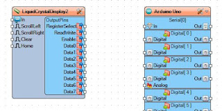
The Details of the LCD Setup Seen in my Last Post
Here is the last project that I posted with screenshots and and examples of how I created it.
After starting Visuino you need to add the standard LCD component, not the I2C one.
This one gives us the the DATA pins that we need to connect to the Arduino.
Next we add the Text Fields that will display on the LCD. Double Click on the top bar and you will see this come up: The "Elements" window
Now Double Click the words "Text Field", twice.
Those will be added to the left-hand side of this window. You can now close the window.
Select the LCD component and look to the left-hand side of the Visuino window, here you should see the "Properties" of the LCD block. Click the plus folder icon to expand it and you should see this:
"Item 0" is the top row of the LCD and "Item 1" is the bottom row, So for the top row we want to type in "Hello World!" for the "Initial Value" As seen here:
For "Item 1" we need to set the "Row" to "1", as seen here:
The next component we will add is the AnalogSnapshot:
And connect it to the "Text Field2" input:
Then add the "Pulse Generator" and connect it to the "Analog Snapshot1":
Now that you are on the "Pulse Generator", look at the "Properties" for it and modify the "Frequency" to "3":
Following that you can add the "Sine Generator" and connect it to the analog input of the Snapshot:
The "Sine Generator Properties" should stay the same and look like this:
Now for my LCD Shield the connections will be different then a bare LCD sans the Shield, but mine connections look like this:
Now you can save the Visuino sketch and connect up you Arduino and then power it all on to upload it.
Let me know in the Comments how yours went.
Tune in next time for some more on Neo-Pixels...


Nice tutorial, and much more details! :-)
ReplyDeleteThank you!
Now following this, it is really easy to get the LCD working :-)
Excellent tutorial Mr. Roesener, thank you very much!!! I it did with me very ancient LCD 16x2 and I work perfectly, hope to be able to show him promptly the result in video...
ReplyDeleteGood to know it worked out for you! Thanks for the comment.
Deletebonjours , j'aimerais affiché l'étas de mes sortie digital , ( on off) sur mon Lcd shield, et aussi utiliser les boutton sur le shield , (select, left, down ect') Merci de m'aider
ReplyDeleteallo, je pense que vous avez juste besoin de savoir ce que les broches sont pour votre bouclier qui sont reliés aux boutons, et juste briser ceux dans Visuino.
DeleteIls pourraient être différents de chaque fabricant qui rend les boucliers.
[Google a aidé à traduire cette]
merci , moi je sais que sais le A0 , qui faite les 4 boutton , je analog = 200 = left (exemple) comment je le rentre dedans visuino ? Merci je sais juste pas comment mettre les block , je débute dans visuino
DeleteYes very nice, easy to follow
ReplyDelete