Showing posts with label Shield. Show all posts

Thursday, July 30, 2015

Raspberry Pi Tips and Tricks and AlaMode Setup - [Part 3]

Experiment with the AlaMode and Visuino


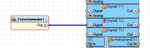
Here you can see the Alamode hooked up to a FTDI cable that is connected to my Computer. So I wanted to find out if I could program it in Visuino, so I opened the program and for a simple test I just hooked up a Pulse Generator to PIN 12, 
since I already had an LED connected form the last blog post.  I used the default of the UNO board type, because that is what is compatible with the AlaMode.


Then I uploaded the Arduino IDE code to the AlaMode using the COM port for the FTDI cable and then unplugged the FTDI cable. Next added the Brick Shield to the AlaMode and powered it via the micro-USB connector after changing P16 to the OFF position.  This setting allows the board to use the micro-USB as it's power source without damaging the board.


When I plugged the AlaMode in the green LED starting blinking away, almost like I planned it  :)  

Following this I added a second LED to the Visuino sketch and went through the procedure again.  


Since I didn't want them to blink at the same rate I changed the Frequency of the second, red LED to 0.5, as seem above.

And now you get to see this final piece in action.


NEXT TIME: I visit the pcDuino and what it can do as a Linux board and how to hook up Arduino Shields to it.


Saturday, July 18, 2015

Raspberry Pi Tips and Tricks and AlaMode Setup - [Part 2]

Setting up the Alamode for a Brick Set Shield


In this post I will show you how to setup the Alamode for use with the Seeed Studio Brick Set.  Above you can see the Brick Shield on top of my Alamode on top on my Model B.

All that is needed is to place the shield on top of the Alamode and add power to the Pi.  There's a power LED on the shield that indicates that it has power and is ready for action.

Next we load a lesson from the PDF that I have linked below:
https://dl.dropboxusercontent.com/u/30598156/brickbook-word-v1-03.pdf

I have even added the lessons to my GitHub account page for ease of use:
https://github.com/SalvorinFex/RasPi-Testing/tree/master/INO%20Files/Brick%20Lessons


Here I have Lesson #1 loaded onto the Alamode and when I press the the button the LED stays on as long as I hold the button down.


Next up is Lesson #2, this one uses a Tilt Switch and 2 LEDs, Green for normal and Red for tilted.


You can use the Brick Set with a standard Arduino, but what's the fun in that  :)

Next Time:  I will connect to the Alamode with out the Pi and use the FTDI cable and try to recreate some of these lessons using the Visual IDE: Visuino!


Wednesday, July 8, 2015

Raspberry Pi Tips and Tricks and AlaMode Setup - [Part 1]

Tips for the Raspberry Pi


I have been using my various Pis for going on 2 years now and have done some projects that worked and some that didn't.  I have found some tips that I thought I should pass on.  First off is organizing your SD cards, these little beauties were found at ACE hardware during a sale for a buck each, just $1.


The regular SD cards fit fine and just enough room to slide out when you tip the case over a bit.


Above you can see the size comparison with my Pis in the Coupe cases by Pimoroni. I really like these Pi cases mainly because they allow full access to the GPIO headers and all the ports and look great!

Another Tip for you is if you have several SD cards for your Pis and there isn't room to label them with what you might be doing with each one, I create a "Projects" file on the desktop of each one so I can quickly look at it to see what is installed and what I had planned for it.  I use 'Abiword' for mine but you can use whatever you choose.


The Alamode Board


The Alamode is a board that adds an Arduino MCU to your Pi and allows you to program it with the Linux version of the Arduino IDE.  It's even on sale right now through the MakerShed.com website.

Now to adding the Alamode to the Pi, it just plugs into the GPIO header of the Pi just like a HAT would.

I am just using my Model B but the Alamode is compatible with the B+ and 2 B.

There are steps to get Raspbian setup for the Alamode that can be found here: http://bit.ly/1UCap1b
It is quite lengthy so I won't re-hash the whole thing here but it should not be too difficult to figure out.

Part of those steps is to install the Arduino IDE for Raspbian, version 1.0.1 to be precise.


Even though it's an older version is still functions just fine for everything I have thrown at it.

Next time:  I will visit the Seeed Electronic Brick Starter Kit and compiling some lessons from a PDF related to the Brick set using the Alamode and the Pi.


Friday, June 5, 2015

LCD Shield in Visuino - Tutorial/Experiment - Part 2: The Details

The Details of the LCD Setup Seen in my Last Post

Here is the last project that I posted with screenshots and and examples of how I created it.

After starting Visuino you need to add the standard LCD component, not the I2C one.


This one gives us the the DATA pins that we need to connect to the Arduino.

Next we add the Text Fields that will display on the LCD.  Double Click on the top bar and you will see this come up: The "Elements" window


Now Double Click the words "Text Field", twice.


Those will be added to the left-hand side of this window.  You can now close the window.

Select the LCD component and look to the left-hand side of the Visuino window, here you should see the "Properties" of the LCD block.  Click the plus folder icon to expand it and you should see this:


"Item 0" is the top row of the LCD and "Item 1" is the bottom row, So for the top row we want to type in "Hello World!" for the "Initial Value" As seen here:


For "Item 1" we need to set the "Row" to "1", as seen here:


The next component we will add is the AnalogSnapshot:


And connect it to the "Text Field2" input:


Then add the "Pulse Generator" and connect it to the "Analog Snapshot1":


Now that you are on the "Pulse Generator", look at the "Properties" for it and modify the "Frequency" to "3":


Following that you can add the "Sine Generator" and connect it to the analog input of the Snapshot:


The "Sine Generator Properties" should stay the same and look like this:


Now for my LCD Shield the connections will be different then a bare LCD sans the Shield, but mine connections look like this:


Now you can save the Visuino sketch and connect up you Arduino and then power it all on to upload it.

Let me know in the Comments how yours went.

Tune in next time for some more on Neo-Pixels...


Tuesday, June 2, 2015

LCD Shield in Visuino - Tutorial/Experiment

Testing the New LCD Components in Visuino

Next test I am doing is with the LCD Shield that I picked up with I Gift Card.  Since the LCD component was just added to Beta 35 of Visuino I thought it was very timely to test this.

This is the LCD Shield that I will be using: 


And I used my Freetronics Eleven board for this test, after some help in the basic sketch in Visuino from the creator, Boian Mitov, we came up with this: 


We get a nice Hello World! on the first line and a SINE number on the second.


I have uploaded the Visuino file here.

If you are interested in this program, please visit www.visuino.com for details on joining the Beta Dev Community on Google Plus.