Friday, October 2, 2015

Running a generic Neo-Pixel 4x4 panel on the Teensy - Experiment

Starting with a basic Teensy LC and a generic 4x4 Neo-Pixel panel and Visuino I was able to make a 16 RGB LED light display, just with an included Visuino Demo.

First I started with Visuino Beta 65 and the Demo file, MixedGroupsDemo.owarduino.  

Then I switched the boards section to the Teensy LC.


In the Demo file, I added a 6th pixel to the third group to account for the difference in the Demo's 15 RGB pixels and my panel 16 RGB pixels.


Please note the 3rd group here, 
the GREEN one is a 6, not a 5


Next, without any further delay, is the Video, 
that I know you all have been waiting for.


Wednesday, September 30, 2015

Using the pcDuino with the Joey Hurdy 3x3x3 LED Cube - Experiment


About 6 months ago I bought the Joey Hurdy LED 3x3x3 led Cube for the Arduino platform.  While soldering it together wasn't easy, once I had the basics of the LED placement down it went pretty quickly.  Makershed.com has it on sale right now for under $10
http://www.makershed.com/products/joey-hudy-2-3x3x3-led-cube-arduino-shield

Just recently I got a pcDuino, which is a Linux based Arduino platform with the Inputs and Outputs of an Arduino UNO.  So the thought occurred to me, why not see if they work together. 

So, I grabbed the code, which can be downloaded here:
https://jumpshare.com/v/URgEXYU9GrkOqMZgnhhb
Copied it to an USB flash drive and then loaded it in the pcDuino's Arduino IDE, which is running 1.5.3 beta for Linux.


Once I uploaded it it did run, but I noticed something odd, it ran much faster on the pcDuino than on an actual UNO.  My thought on this is because the pcDuino is running at 1GHz there must be some timing issues that aren't accounted for when running a a much faster processor.  I will need to research this some more.


This is a standard UNO with the Cube running.


This is the Cube running faster on a pcDuino.


If you have any insights that I haven't covered please leave a comment below!

I have not been able to post blog updates as I would have liked to, this is due to some personal issues that we are having that should be taken care of in a few months time, at that point, hopefully blog posts will continue with some regularity.


Thursday, July 30, 2015

Raspberry Pi Tips and Tricks and AlaMode Setup - [Part 3]

Experiment with the AlaMode and Visuino


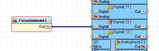
Here you can see the Alamode hooked up to a FTDI cable that is connected to my Computer. So I wanted to find out if I could program it in Visuino, so I opened the program and for a simple test I just hooked up a Pulse Generator to PIN 12, 
since I already had an LED connected form the last blog post.  I used the default of the UNO board type, because that is what is compatible with the AlaMode.


Then I uploaded the Arduino IDE code to the AlaMode using the COM port for the FTDI cable and then unplugged the FTDI cable. Next added the Brick Shield to the AlaMode and powered it via the micro-USB connector after changing P16 to the OFF position.  This setting allows the board to use the micro-USB as it's power source without damaging the board.


When I plugged the AlaMode in the green LED starting blinking away, almost like I planned it  :)  

Following this I added a second LED to the Visuino sketch and went through the procedure again.  


Since I didn't want them to blink at the same rate I changed the Frequency of the second, red LED to 0.5, as seem above.

And now you get to see this final piece in action.


NEXT TIME: I visit the pcDuino and what it can do as a Linux board and how to hook up Arduino Shields to it.


Saturday, July 18, 2015

Raspberry Pi Tips and Tricks and AlaMode Setup - [Part 2]

Setting up the Alamode for a Brick Set Shield


In this post I will show you how to setup the Alamode for use with the Seeed Studio Brick Set.  Above you can see the Brick Shield on top of my Alamode on top on my Model B.

All that is needed is to place the shield on top of the Alamode and add power to the Pi.  There's a power LED on the shield that indicates that it has power and is ready for action.

Next we load a lesson from the PDF that I have linked below:
https://dl.dropboxusercontent.com/u/30598156/brickbook-word-v1-03.pdf

I have even added the lessons to my GitHub account page for ease of use:
https://github.com/SalvorinFex/RasPi-Testing/tree/master/INO%20Files/Brick%20Lessons


Here I have Lesson #1 loaded onto the Alamode and when I press the the button the LED stays on as long as I hold the button down.


Next up is Lesson #2, this one uses a Tilt Switch and 2 LEDs, Green for normal and Red for tilted.


You can use the Brick Set with a standard Arduino, but what's the fun in that  :)

Next Time:  I will connect to the Alamode with out the Pi and use the FTDI cable and try to recreate some of these lessons using the Visual IDE: Visuino!


Wednesday, July 8, 2015

Raspberry Pi Tips and Tricks and AlaMode Setup - [Part 1]

Tips for the Raspberry Pi


I have been using my various Pis for going on 2 years now and have done some projects that worked and some that didn't.  I have found some tips that I thought I should pass on.  First off is organizing your SD cards, these little beauties were found at ACE hardware during a sale for a buck each, just $1.


The regular SD cards fit fine and just enough room to slide out when you tip the case over a bit.


Above you can see the size comparison with my Pis in the Coupe cases by Pimoroni. I really like these Pi cases mainly because they allow full access to the GPIO headers and all the ports and look great!

Another Tip for you is if you have several SD cards for your Pis and there isn't room to label them with what you might be doing with each one, I create a "Projects" file on the desktop of each one so I can quickly look at it to see what is installed and what I had planned for it.  I use 'Abiword' for mine but you can use whatever you choose.


The Alamode Board


The Alamode is a board that adds an Arduino MCU to your Pi and allows you to program it with the Linux version of the Arduino IDE.  It's even on sale right now through the MakerShed.com website.

Now to adding the Alamode to the Pi, it just plugs into the GPIO header of the Pi just like a HAT would.

I am just using my Model B but the Alamode is compatible with the B+ and 2 B.

There are steps to get Raspbian setup for the Alamode that can be found here: http://bit.ly/1UCap1b
It is quite lengthy so I won't re-hash the whole thing here but it should not be too difficult to figure out.

Part of those steps is to install the Arduino IDE for Raspbian, version 1.0.1 to be precise.


Even though it's an older version is still functions just fine for everything I have thrown at it.

Next time:  I will visit the Seeed Electronic Brick Starter Kit and compiling some lessons from a PDF related to the Brick set using the Alamode and the Pi.


Friday, June 26, 2015

Raspberry Pi and Bitcoin Mining - Tutorial / Experiment [Minera]

This is a basic tutorial on how to setup your Raspberry Pi for Bitcoin mining using the image for Minera


Minera is an all in one solution for Bitcoin mining on the Raspberry Pi and is relatively easy to setup.  

First you need to Download the Image file which can be found here:  http://getminera.com/, there is also an option for a Manual Install  but that is for full desktops/laptops not a Pi install.

Next using one off the Image writing instructions listed on this link, you need to write it to an SD card:
https://www.raspberrypi.org/documentation/installation/installing-images/README.md
I would recommend a 4 GB SD card and in this case the Class of the card doesn't really matter, I used a Class 4 Kingston micro card that I hadn't done anything with in a while.  

After writing the card all you need to do is put it into your Pi, I used a B+, and connect Network, powered USB hub with your miners plugged in and either a wired or wireless network connection, then add the power plug and wait about 3-5 minutes.

Next, you need to, most likely, after you power the Pi on, go to http://minera on your home network.  I tried this on mine, but I am running a domain and the DNS hadn't propagated yet, so I just went to my router and found out the IP address of the Pi that way and just typed in 192.169.1.20.

You will be brought to a screen that requires a login, the default password is minera .  Next you should see something like this on your web browser of choice.

This screenshot was my setup after running for about 15 minutes.

 There has been an upgrade to the version of Minera, to 0.6.0, since I took this screenshot, but I have not logged into it since I am away from home right now to update this capture.  There are some updated screenshots here:  http://getminera.com/#screenshots

The next steps are to go to Settings on the left hand side and input your Pool and Miner settings that you can customize on the fly.  I don't have any more screenshots that I took because they have my BTC Wallet info in them and I didn't have a chance to clean them before posting.

For most help related inquiries answers can either be found on the GitHub project page, here: https://github.com/michelem09/minera or the Forum page here: https://bitcointalk.org/index.php?topic=596620.0

Please let me know if you have any question in the comments below and I will get back to you as soon as I can.

Friday, June 19, 2015

ESP8266 Temperature and Humidity Web Server - Experiment [Part 2]

Not the Raspberry Pi Experiment as promised - But a Learning Experience!  [Part 2]

This is a continuation of this first part:

Here is the link to the wiring diagram the I used for this project: https://learn.adafruit.com/esp8266-temperature-slash-humidity-webserver/wiring

Here is a link to the INO file source code for programming this board: http://bit.ly/DHTServer


Here is the diagram that I used to build out this circuit:

Last night I started soldering this together and took some pictures along the way of my progress.

Here is the board as we saw it in the first part of this series, with an added USB port for power.


I added a USB port so I could power it from a little power pack that I have, using a USB A to USB A cable from a hard drive.


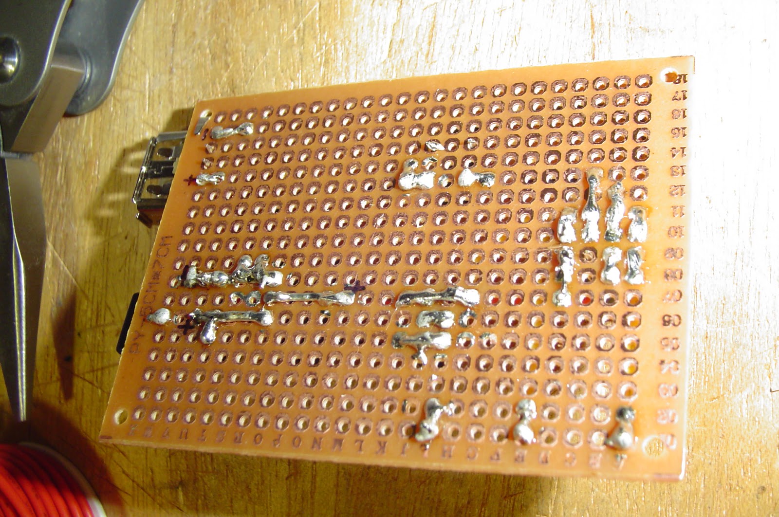
The solder side of the board isn't very pretty.


The button you see here is used to program the ESP8266.  You power on the board with the button depressed and then let go of it, program it through the Arduino IDE and power cycle the board again.


Almost done now, just a couple more connections to make.


Here we have the completed board, the pins you see in the lower left are for programming the ESP8266.


After completing the board I tested the output voltage at several locations and they all seemed to run at about 3.25V, within acceptable tolerances.


Added the missing components and tested it, and It WORKS!


I hope that this was informative and useful for you, Please Comment below if you have any questions regarding this project!


Thanks for reading!