Showing posts with label Adafruit. Show all posts

Saturday, December 5, 2015

Raspberry Pi Zero - Screenshots - Sunday Dec. 6th Update!

Here are the screenshots that I promised in my first post about the Pi Zero.


First off, we have a "Jessie" screenshot of the Pi 2 B,
you can see that it is running at 900mHz and that it has almost 1gb of RAM.


Secondly, we have the same SD image of "Jessie" in the Zero and
it shows it running at 1gHz with 512mbs of RAM.


Here is the next shot of the default web browser with a DuckDuckGo search page, GIMP in the lower right-hand corner and the Task Manager; showing about 1/3 of the RAM being used with very little CPU time.


Finally we have the MagPi website up, Libre Office Writer and the Task Manager shows the about the same amount of RAM being used as before, but due to the activity of the web page the CPU is maxed out, which isn't surprising.


I will add to this same page with additional screenshots Sunday afternoon.  They will include the menus off of the "Menu" button.


Please stay tuned!


Sunday Dec. 6th.  Update!
The Following screenshots, are of the the items in the MENU bar, but I was not able to take direct screenshots of it.  These are the same items just in their 'file explorer' under 'Applications' view, instead.

Accessories

Games

Internet

Office [Libre Office]

Preferences

Programming

Applications


Thursday, December 3, 2015

Raspberry Pi Zero - Initial Thoughts

My Pi Zero arrived this evening and here are some of my first experiences with it.

I bought mine from Adafruit in the wee hours of the 26th and right after I checked out and confirmed my order, I went back to the page for the Pi Zero and saw that it had already sold out.  It has been re-stocked at least twice, that I know of, and has sold out again within an half an hour each time.

Here is what I got:  Pi Zero, Pi Protector, HDMI Mini to Standard HDMI adapter, USB OTG host cable, and 2 sets of headers for the GPIO; the straight ones - male to male and male to 90° angle female.  All for less than the cost of 5 *bucks coffee drinks.


The Adafruit box, in it's glory, at least to me.  
I have had many of these boxes arrive before but this one seemed to be special


What appeared inside, after I pulled the pulled the important stuff to the surface.


Now the Zero out of it's ESD bag.


Here we see the Zero hooked up and some other items for size comparison.
The standard SD card shows that this is just about the same size, in height and about 3 across in width.


This is the current USB hub that I am using with power.


As prepared as I was, I still ran into some snags.  First, before it arrived I imaged a couple of micro SD cards with the latest Raspbian, Jessie on them.  So, when I had it setup and connected I just plugged one in and booted it up.  Upon start-up I was greeted by the new interface and realized that I couldn't do any updates yet, due to, my fault really, in unable to find the WPA-GUI program.  This was my first issue that I researched, from another computer and found the answer pretty quickly.  The Network icon down near the clock had all the functionality of the old program but none of the clunky stuff , which is great!

After this, I loaded the new Add-Remove Software program, and found it really easy to use, with the caveat being, that you can only use either the Install OR the Uninstall at one time, you can't install one thing while uninstalling something else.

One thing that I did find, while using some of my Wheezy cards, I had to update them with  my Pi 2 B, first, then load them up in the Zero, so having a B+ and/or a Pi 2 B very handy if you want/need to keep Wheezy around for use in your Zero.

Next time:  Some screenshots and some stats for your enjoyment!


Friday, October 2, 2015

Running a generic Neo-Pixel 4x4 panel on the Teensy - Experiment

Starting with a basic Teensy LC and a generic 4x4 Neo-Pixel panel and Visuino I was able to make a 16 RGB LED light display, just with an included Visuino Demo.

First I started with Visuino Beta 65 and the Demo file, MixedGroupsDemo.owarduino.  

Then I switched the boards section to the Teensy LC.


In the Demo file, I added a 6th pixel to the third group to account for the difference in the Demo's 15 RGB pixels and my panel 16 RGB pixels.


Please note the 3rd group here, 
the GREEN one is a 6, not a 5


Next, without any further delay, is the Video, 
that I know you all have been waiting for.


Thursday, July 30, 2015

Raspberry Pi Tips and Tricks and AlaMode Setup - [Part 3]

Experiment with the AlaMode and Visuino


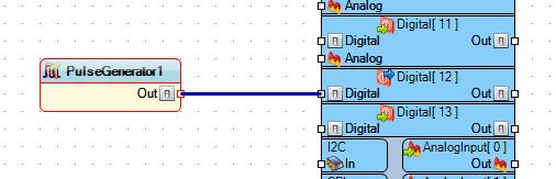
Here you can see the Alamode hooked up to a FTDI cable that is connected to my Computer. So I wanted to find out if I could program it in Visuino, so I opened the program and for a simple test I just hooked up a Pulse Generator to PIN 12, 
since I already had an LED connected form the last blog post.  I used the default of the UNO board type, because that is what is compatible with the AlaMode.


Then I uploaded the Arduino IDE code to the AlaMode using the COM port for the FTDI cable and then unplugged the FTDI cable. Next added the Brick Shield to the AlaMode and powered it via the micro-USB connector after changing P16 to the OFF position.  This setting allows the board to use the micro-USB as it's power source without damaging the board.


When I plugged the AlaMode in the green LED starting blinking away, almost like I planned it  :)  

Following this I added a second LED to the Visuino sketch and went through the procedure again.  


Since I didn't want them to blink at the same rate I changed the Frequency of the second, red LED to 0.5, as seem above.

And now you get to see this final piece in action.


NEXT TIME: I visit the pcDuino and what it can do as a Linux board and how to hook up Arduino Shields to it.


Friday, June 19, 2015

ESP8266 Temperature and Humidity Web Server - Experiment [Part 2]

Not the Raspberry Pi Experiment as promised - But a Learning Experience!  [Part 2]

This is a continuation of this first part:

Here is the link to the wiring diagram the I used for this project: https://learn.adafruit.com/esp8266-temperature-slash-humidity-webserver/wiring

Here is a link to the INO file source code for programming this board: http://bit.ly/DHTServer


Here is the diagram that I used to build out this circuit:

Last night I started soldering this together and took some pictures along the way of my progress.

Here is the board as we saw it in the first part of this series, with an added USB port for power.


I added a USB port so I could power it from a little power pack that I have, using a USB A to USB A cable from a hard drive.


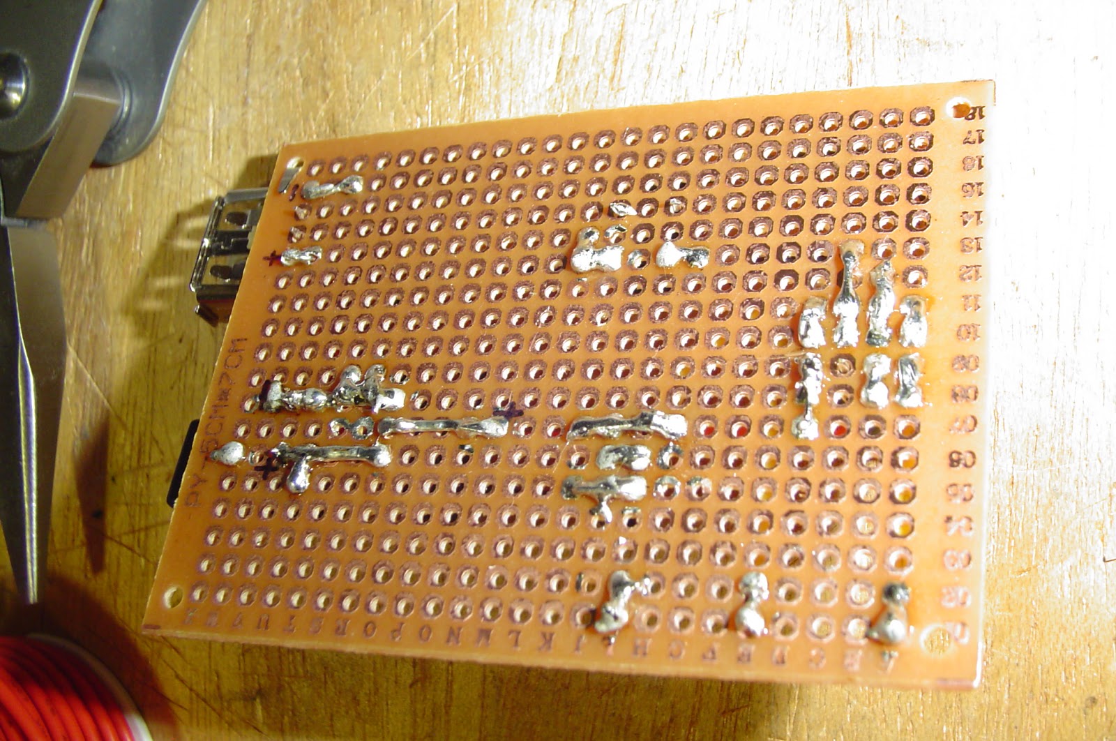
The solder side of the board isn't very pretty.


The button you see here is used to program the ESP8266.  You power on the board with the button depressed and then let go of it, program it through the Arduino IDE and power cycle the board again.


Almost done now, just a couple more connections to make.


Here we have the completed board, the pins you see in the lower left are for programming the ESP8266.


After completing the board I tested the output voltage at several locations and they all seemed to run at about 3.25V, within acceptable tolerances.


Added the missing components and tested it, and It WORKS!


I hope that this was informative and useful for you, Please Comment below if you have any questions regarding this project!


Thanks for reading!


Monday, June 15, 2015

ESP8266 Temperature and Humidity Web Server - Experiment [Part 1]

Not the Raspberry Pi Experiment as promised - But a Learning Experience!  [Part 1]


Since I just received a couple of ESP8266s I wanted to play with them right away.
This project leapt out at me: 
All details about components and the code can be found there!

Also, since I had most of the parts on hand already it was, as they say, 'a no brainer'.

This will also be different than my other posts, as it will be in at least 2 parts, maybe more.
This first part, will be building the circuit on the breadboard and the start of the through-hole circuit design.

So, while my circuit on the breadboard does work, it's not pretty:


Some minor changes here are the breadboard's power, I used a specialty power board so I can power it via USB and my DHT22 already has the resistor built into it and only the 3 main pins coming out of it. 


The button is only used for programming the ESP8266 module and nothing else.  Also, not seen here is the USB to TTL wires that allows you to do the programming.


Once I did program it and shut it down and then power it on the web page came up and displayed the temp on one address by adding /temp to the IP and the /humidity to the IP for the other.


Now for the learning part; 

I wanted to get this off of a breadboard and on to a through hole circuit board:


As you can see here I started with the basics, the 2.1mm power plug, the LD1117-3.3 regulator and since I wanted to be able to remove/replace the DHT22 and the ESP8266, I used male-female sockets for those two.  

Below you can see the back of the board and my creative use of the long leads of the LD1117:


Please ask questions, should you have any!!


Next Time:  I venture into soldering this together and testing the new board.

Part 2 can be found here: 


Sunday, June 7, 2015

Using the Trinket Pro with the Neo-Pixel Bar - Experiment

Experiment with the Trinket Pro and Neo-Pixels

I got a HackaDay Trinket Pro about 6 months ago and it is a great little board.


However, since only the Trinket is in Visuino and very experimental at this point I am venturing into unknown territory...I like living on the edge! ;)  
So, I wanted to test out the Neo-Pixel Bar that I got, it has 8 Neo-Pixels on it and I added some 0.1 pins to the 4 connectors at the bottom of it, so I could just plug it into a breadboard.


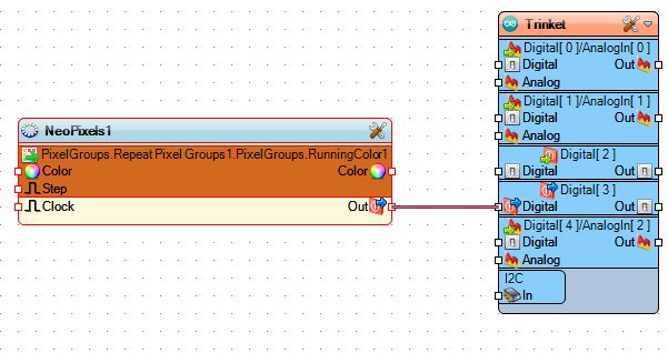
For this sketch I started with the Demo NeoPixelRepeatDemo.owarduino that is included with the Visuino base install.  I just changed the board to the Trinket, which I will have to use for the Trinket Pro in Visuino and just be careful of what Pins I setup.  I decided to use Pin 3 for the Din on the Neo Bar, as seen here:


The other part of the Demo are these components:


To build this up yourself, first you'd add the Neo-Pixel:


Next you will add the "Repeat Pixels Groups" to it by double clicking and then double 
clicking this option:


Once in the "Properties" for the Neo, find "Pixel Groups" and click on the 3 red dots in a row:


 Then you choose the "Running Color" option and exit this screen:


You should have what you see here:


Next add the "Random Color" generator and connect it to the "Color" Pin:

And lastly is the "Clock Generator" added to the "Step" Pin:


After saving my changes I hooked up the board and sent it to the Adafruit version Arduino IDE, which includes the boards that they make in one simple package.  As of this writing that is version 1.6.4 which you can get here: 
I just unzipped it to a Arduino folder on my C: drive then changed the Visuino Settings to point to it.


So, by default the setup for this are repeating random pixels that rotate down the bar, that is broken up into a group of 4 pixels,  this setting can be seen here:


Here is an example of the 4 group Neos in action:


But I wanted to see all 8 pixels as different random colors so I changed this number to 8. Then here is an example of that:


That worked out great and I used some of my Visuino knowledge to modify an included Demo and came out the way I wanted it to.


Next Time: I will visit the Raspberry Pi and it's bound to be something cool  ;)