Experiment with the AlaMode and Visuino

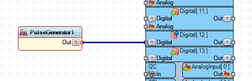
Here you can see the Alamode hooked up to a FTDI cable that is connected to my Computer. So I wanted to find out if I could program it in Visuino, so I opened the program and for a simple test I just hooked up a Pulse Generator to PIN 12,
since I already had an LED connected form the last blog post. I used the default of the UNO board type, because that is what is compatible with the AlaMode.

Then I uploaded the Arduino IDE code to the AlaMode using the COM port for the FTDI cable and then unplugged the FTDI cable. Next added the Brick Shield to the AlaMode and powered it via the micro-USB connector after changing P16 to the OFF position. This setting allows the board to use the micro-USB as it's power source without damaging the board.

When I plugged the AlaMode in the green LED starting blinking away, almost like I planned it :)
Following this I added a second LED to the Visuino sketch and went through the procedure again.


Since I didn't want them to blink at the same rate I changed the Frequency of the second, red LED to 0.5, as seem above.
And now you get to see this final piece in action.
NEXT TIME: I visit the pcDuino and what it can do as a Linux board and how to hook up Arduino Shields to it.


Nice, short and easy to follow! :-)
ReplyDeleteA very good starting point for AlaMode!
Did you use "Arduino Uno" as a board type in Visuino when programming AlaMode ?
ReplyDeleteYes, That is what is compatible for the AlaMode.
DeleteI will add that to the post.