Showing posts with label LD1117. Show all posts

Friday, June 19, 2015

ESP8266 Temperature and Humidity Web Server - Experiment [Part 2]

Not the Raspberry Pi Experiment as promised - But a Learning Experience!  [Part 2]

This is a continuation of this first part:

Here is the link to the wiring diagram the I used for this project: https://learn.adafruit.com/esp8266-temperature-slash-humidity-webserver/wiring

Here is a link to the INO file source code for programming this board: http://bit.ly/DHTServer


Here is the diagram that I used to build out this circuit:

Last night I started soldering this together and took some pictures along the way of my progress.

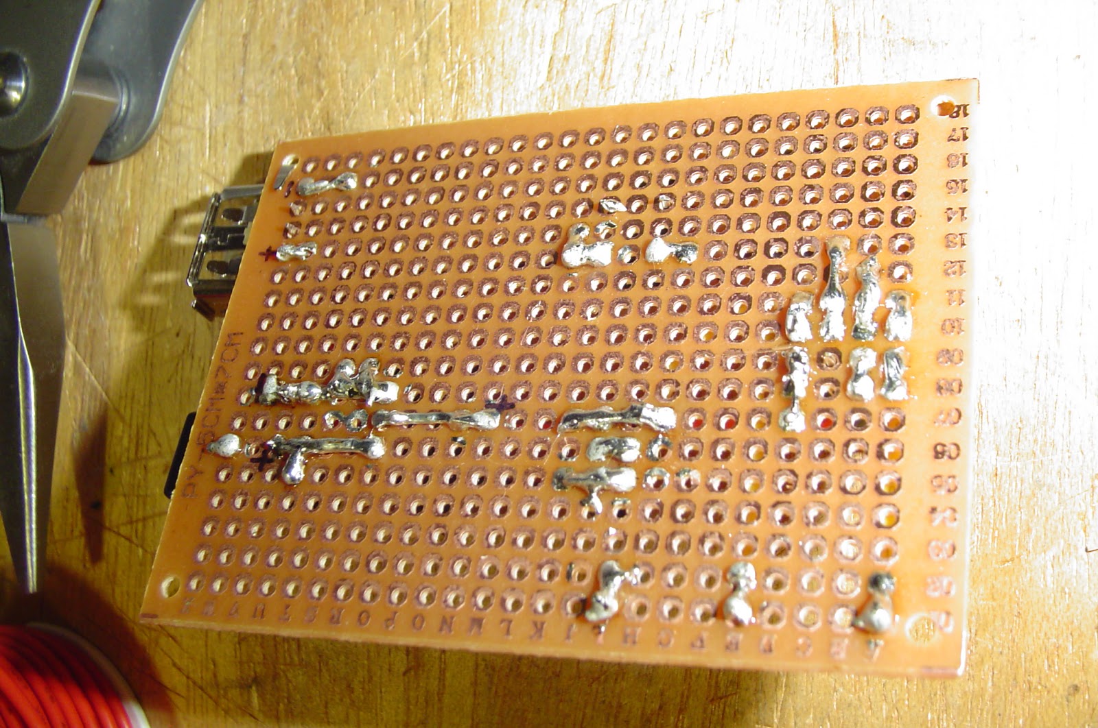
Here is the board as we saw it in the first part of this series, with an added USB port for power.


I added a USB port so I could power it from a little power pack that I have, using a USB A to USB A cable from a hard drive.


The solder side of the board isn't very pretty.


The button you see here is used to program the ESP8266.  You power on the board with the button depressed and then let go of it, program it through the Arduino IDE and power cycle the board again.


Almost done now, just a couple more connections to make.


Here we have the completed board, the pins you see in the lower left are for programming the ESP8266.


After completing the board I tested the output voltage at several locations and they all seemed to run at about 3.25V, within acceptable tolerances.


Added the missing components and tested it, and It WORKS!


I hope that this was informative and useful for you, Please Comment below if you have any questions regarding this project!


Thanks for reading!


Monday, June 15, 2015

ESP8266 Temperature and Humidity Web Server - Experiment [Part 1]

Not the Raspberry Pi Experiment as promised - But a Learning Experience!  [Part 1]


Since I just received a couple of ESP8266s I wanted to play with them right away.
This project leapt out at me: 
All details about components and the code can be found there!

Also, since I had most of the parts on hand already it was, as they say, 'a no brainer'.

This will also be different than my other posts, as it will be in at least 2 parts, maybe more.
This first part, will be building the circuit on the breadboard and the start of the through-hole circuit design.

So, while my circuit on the breadboard does work, it's not pretty:


Some minor changes here are the breadboard's power, I used a specialty power board so I can power it via USB and my DHT22 already has the resistor built into it and only the 3 main pins coming out of it. 


The button is only used for programming the ESP8266 module and nothing else.  Also, not seen here is the USB to TTL wires that allows you to do the programming.


Once I did program it and shut it down and then power it on the web page came up and displayed the temp on one address by adding /temp to the IP and the /humidity to the IP for the other.


Now for the learning part; 

I wanted to get this off of a breadboard and on to a through hole circuit board:


As you can see here I started with the basics, the 2.1mm power plug, the LD1117-3.3 regulator and since I wanted to be able to remove/replace the DHT22 and the ESP8266, I used male-female sockets for those two.  

Below you can see the back of the board and my creative use of the long leads of the LD1117:


Please ask questions, should you have any!!


Next Time:  I venture into soldering this together and testing the new board.

Part 2 can be found here: