Friday, June 26, 2015

Raspberry Pi and Bitcoin Mining - Tutorial / Experiment [Minera]

This is a basic tutorial on how to setup your Raspberry Pi for Bitcoin mining using the image for Minera


Minera is an all in one solution for Bitcoin mining on the Raspberry Pi and is relatively easy to setup.  

First you need to Download the Image file which can be found here:  http://getminera.com/, there is also an option for a Manual Install  but that is for full desktops/laptops not a Pi install.

Next using one off the Image writing instructions listed on this link, you need to write it to an SD card:
https://www.raspberrypi.org/documentation/installation/installing-images/README.md
I would recommend a 4 GB SD card and in this case the Class of the card doesn't really matter, I used a Class 4 Kingston micro card that I hadn't done anything with in a while.  

After writing the card all you need to do is put it into your Pi, I used a B+, and connect Network, powered USB hub with your miners plugged in and either a wired or wireless network connection, then add the power plug and wait about 3-5 minutes.

Next, you need to, most likely, after you power the Pi on, go to http://minera on your home network.  I tried this on mine, but I am running a domain and the DNS hadn't propagated yet, so I just went to my router and found out the IP address of the Pi that way and just typed in 192.169.1.20.

You will be brought to a screen that requires a login, the default password is minera .  Next you should see something like this on your web browser of choice.

This screenshot was my setup after running for about 15 minutes.

 There has been an upgrade to the version of Minera, to 0.6.0, since I took this screenshot, but I have not logged into it since I am away from home right now to update this capture.  There are some updated screenshots here:  http://getminera.com/#screenshots

The next steps are to go to Settings on the left hand side and input your Pool and Miner settings that you can customize on the fly.  I don't have any more screenshots that I took because they have my BTC Wallet info in them and I didn't have a chance to clean them before posting.

For most help related inquiries answers can either be found on the GitHub project page, here: https://github.com/michelem09/minera or the Forum page here: https://bitcointalk.org/index.php?topic=596620.0

Please let me know if you have any question in the comments below and I will get back to you as soon as I can.

Friday, June 19, 2015

ESP8266 Temperature and Humidity Web Server - Experiment [Part 2]

Not the Raspberry Pi Experiment as promised - But a Learning Experience!  [Part 2]

This is a continuation of this first part:

Here is the link to the wiring diagram the I used for this project: https://learn.adafruit.com/esp8266-temperature-slash-humidity-webserver/wiring

Here is a link to the INO file source code for programming this board: http://bit.ly/DHTServer


Here is the diagram that I used to build out this circuit:

Last night I started soldering this together and took some pictures along the way of my progress.

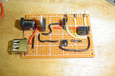
Here is the board as we saw it in the first part of this series, with an added USB port for power.


I added a USB port so I could power it from a little power pack that I have, using a USB A to USB A cable from a hard drive.


The solder side of the board isn't very pretty.


The button you see here is used to program the ESP8266.  You power on the board with the button depressed and then let go of it, program it through the Arduino IDE and power cycle the board again.


Almost done now, just a couple more connections to make.


Here we have the completed board, the pins you see in the lower left are for programming the ESP8266.


After completing the board I tested the output voltage at several locations and they all seemed to run at about 3.25V, within acceptable tolerances.


Added the missing components and tested it, and It WORKS!


I hope that this was informative and useful for you, Please Comment below if you have any questions regarding this project!


Thanks for reading!


Monday, June 15, 2015

ESP8266 Temperature and Humidity Web Server - Experiment [Part 1]

Not the Raspberry Pi Experiment as promised - But a Learning Experience!  [Part 1]


Since I just received a couple of ESP8266s I wanted to play with them right away.
This project leapt out at me: 
All details about components and the code can be found there!

Also, since I had most of the parts on hand already it was, as they say, 'a no brainer'.

This will also be different than my other posts, as it will be in at least 2 parts, maybe more.
This first part, will be building the circuit on the breadboard and the start of the through-hole circuit design.

So, while my circuit on the breadboard does work, it's not pretty:


Some minor changes here are the breadboard's power, I used a specialty power board so I can power it via USB and my DHT22 already has the resistor built into it and only the 3 main pins coming out of it. 


The button is only used for programming the ESP8266 module and nothing else.  Also, not seen here is the USB to TTL wires that allows you to do the programming.


Once I did program it and shut it down and then power it on the web page came up and displayed the temp on one address by adding /temp to the IP and the /humidity to the IP for the other.


Now for the learning part; 

I wanted to get this off of a breadboard and on to a through hole circuit board:


As you can see here I started with the basics, the 2.1mm power plug, the LD1117-3.3 regulator and since I wanted to be able to remove/replace the DHT22 and the ESP8266, I used male-female sockets for those two.  

Below you can see the back of the board and my creative use of the long leads of the LD1117:


Please ask questions, should you have any!!


Next Time:  I venture into soldering this together and testing the new board.

Part 2 can be found here: 


Sunday, June 7, 2015

Using the Trinket Pro with the Neo-Pixel Bar - Experiment

Experiment with the Trinket Pro and Neo-Pixels

I got a HackaDay Trinket Pro about 6 months ago and it is a great little board.


However, since only the Trinket is in Visuino and very experimental at this point I am venturing into unknown territory...I like living on the edge! ;)  
So, I wanted to test out the Neo-Pixel Bar that I got, it has 8 Neo-Pixels on it and I added some 0.1 pins to the 4 connectors at the bottom of it, so I could just plug it into a breadboard.


For this sketch I started with the Demo NeoPixelRepeatDemo.owarduino that is included with the Visuino base install.  I just changed the board to the Trinket, which I will have to use for the Trinket Pro in Visuino and just be careful of what Pins I setup.  I decided to use Pin 3 for the Din on the Neo Bar, as seen here:


The other part of the Demo are these components:


To build this up yourself, first you'd add the Neo-Pixel:


Next you will add the "Repeat Pixels Groups" to it by double clicking and then double 
clicking this option:


Once in the "Properties" for the Neo, find "Pixel Groups" and click on the 3 red dots in a row:


 Then you choose the "Running Color" option and exit this screen:


You should have what you see here:


Next add the "Random Color" generator and connect it to the "Color" Pin:

And lastly is the "Clock Generator" added to the "Step" Pin:


After saving my changes I hooked up the board and sent it to the Adafruit version Arduino IDE, which includes the boards that they make in one simple package.  As of this writing that is version 1.6.4 which you can get here: 
I just unzipped it to a Arduino folder on my C: drive then changed the Visuino Settings to point to it.


So, by default the setup for this are repeating random pixels that rotate down the bar, that is broken up into a group of 4 pixels,  this setting can be seen here:


Here is an example of the 4 group Neos in action:


But I wanted to see all 8 pixels as different random colors so I changed this number to 8. Then here is an example of that:


That worked out great and I used some of my Visuino knowledge to modify an included Demo and came out the way I wanted it to.


Next Time: I will visit the Raspberry Pi and it's bound to be something cool  ;)


Friday, June 5, 2015

LCD Shield in Visuino - Tutorial/Experiment - Part 2: The Details

The Details of the LCD Setup Seen in my Last Post

Here is the last project that I posted with screenshots and and examples of how I created it.

After starting Visuino you need to add the standard LCD component, not the I2C one.


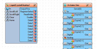
This one gives us the the DATA pins that we need to connect to the Arduino.

Next we add the Text Fields that will display on the LCD.  Double Click on the top bar and you will see this come up: The "Elements" window


Now Double Click the words "Text Field", twice.


Those will be added to the left-hand side of this window.  You can now close the window.

Select the LCD component and look to the left-hand side of the Visuino window, here you should see the "Properties" of the LCD block.  Click the plus folder icon to expand it and you should see this:


"Item 0" is the top row of the LCD and "Item 1" is the bottom row, So for the top row we want to type in "Hello World!" for the "Initial Value" As seen here:


For "Item 1" we need to set the "Row" to "1", as seen here:


The next component we will add is the AnalogSnapshot:


And connect it to the "Text Field2" input:


Then add the "Pulse Generator" and connect it to the "Analog Snapshot1":


Now that you are on the "Pulse Generator", look at the "Properties" for it and modify the "Frequency" to "3":


Following that you can add the "Sine Generator" and connect it to the analog input of the Snapshot:


The "Sine Generator Properties" should stay the same and look like this:


Now for my LCD Shield the connections will be different then a bare LCD sans the Shield, but mine connections look like this:


Now you can save the Visuino sketch and connect up you Arduino and then power it all on to upload it.

Let me know in the Comments how yours went.

Tune in next time for some more on Neo-Pixels...


Tuesday, June 2, 2015

LCD Shield in Visuino - Tutorial/Experiment

Testing the New LCD Components in Visuino

Next test I am doing is with the LCD Shield that I picked up with I Gift Card.  Since the LCD component was just added to Beta 35 of Visuino I thought it was very timely to test this.

This is the LCD Shield that I will be using: 


And I used my Freetronics Eleven board for this test, after some help in the basic sketch in Visuino from the creator, Boian Mitov, we came up with this: 


We get a nice Hello World! on the first line and a SINE number on the second.


I have uploaded the Visuino file here.

If you are interested in this program, please visit www.visuino.com for details on joining the Beta Dev Community on Google Plus.